Knowledge Base / FAQ
Below you find the Stealth Knowledge Base / FAQ which contains answers to common questions as well as detailed explanations on technical terms and technology.
-
Are there thermal management issues with sunlight readable LCD’s?
Yes -any high brightness backlight system will consume a significant amount of power, thereby increasing the LCD temperature. The brighter the backlight, the greater the thermal issue. As well, if the LCD is used under direct sunlight additional heat will be generated as a result of sunlight exposure. Temperature issues have been handled through proper thermal management design incorporating passive and active cooling methods. This is extremely important in maintaining overall reliability and long-term operation.
-
How do I know how many NIT’s I require for my application?
Applications will vary depending on the location of the LCD and how much ambient light is available that could cause the display to become washed out or unreadable. As a rule of thumb; notebooks and desktop LCD’s which are generally used in office light conditions are in the 200-250 nit range. For indoor use with uncontrolled or indirect sunlight it is recommended that a display of 500 – 900 nits be used. If the application is outdoors or in direct sunlight then at least 1000 nits and up should be considered.
-
How Does Downgrade Rights for Windows 7 Work?
Note – End of XP Support
April 8, 2014 marked the official end of Windows XP support from Microsoft. On April 8, 2014 security updates will stop being issued for the aging but still popular operating system.
Moving forward Stealth recommends the Windows 7, 64-bit operating system as a base for all of its new and existing systems. If you still require Windows XP for your specific application it can still be provided on new orders upon request by purchasing Windows 7 and exercising your Windows 7 Downgrade rights.
Stealth can provide Windows XP for systems powered up to 3rd Generation Intel Core processors. We also highly recommend the use of up-to-date anti-virus protection to help protect against security threats since Microsoft is no longer supporting it.
How Does Downgrade Rights for Windows 7 Work?
Introduction
Windows 7 is the latest offering in desktop operating systems from Microsoft. In some cases end-users still need to operate with previous versions of O/S such as Windows XP or Vista. As part of Microsoft’s End User License Agreement (EULA), Stealth Computer is an authorized Microsoft OEM and is permitted to offer its customers the ability to run previous versions of XP or Vista Operating Systems.How does this work? – Downgrade to Microsoft XP as an example.
Windows XP is no longer available for purchase from Microsoft. What you are purchasing is a Windows 7 Pro license with product key, installation media along with a service that allows us (with your permission) to exercise your downgrade rights. You will need to purchase a separate license for each computer ordered.When choosing the downgrade option Stealth will preinstall Windows XP Pro, 32-Bit, SP3 on your new machine. You will not be provided with Windows XP Pro media.
What happens if I need to re-load Windows XP Pro?
As per the terms of Microsoft’s downgrade rights, we are unable to provide you with the installation media or a product key for Windows XP Pro. This is supposed to be provided by you, the end user. Since we have media and a product key on file, we utilize these as a courtesy to do the initial installation.
If you need to reinstall Windows XP Pro there are two choices detailed as follows;
Return the PC directly to Stealth Computer (The authorized OEM) for a re-installation of the O/S. Note: nominal charges may apply
or
If you wish to reload Windows XP on your own, you must obtain a copy of the genuine Microsoft Windows XP Pro installation media and a previously activated Windows XP product key. You may use any Windows XP Pro key from a previously activated system. You must use this media and product key to reinstall Windows XP Pro.
After reinstalling please do not activate via the internet. You MUST activate your installation of Windows XP Pro via Microsoft’s telephone activation line. When speaking to a representative tell them that you are exercising your downgrade rights from your Windows 7 Pro license. They will then provide you with an installation ID for you to activate your Win XP Pro re-installation.
You can find additional information on Microsoft’s downgrade rights by clicking, HERE
If you have further questions please contact Stealth.
-
How will fanless computers benefit you?
How will fanless computers benefit you?
Save time/money and reduce the worry. No planned maintenance to clean cooling fans or discovering a clogged fan has shut down your application or process.
No noise! When used with SSD the fanless PC is completely noise free making it ideal for control rooms, audio recording, board rooms, deep thinking and other areas that need to be low in ambient noise.
Numerous designs and configurations to meet your application needs. Deployable in limited space or in rack packaging offering multi I/O, Sealed/Waterproof, DC power, Wireless and more.
Stealth’s fanless computer products are an excellent fit for many applications including; Embedded Control Audio/Video recording, Digital Signs, Interactive Kiosks, Thin-Clients, Human/Machine Interface and your next applications.Built to meet your applications
- No noise and low power consumption
- Solid State Drives (SSD)
- Small Rugged Chassis Designs
- Mobile, DC Power Input, Multi I/O
- Sealed/Waterproof, Multi-LAN Networking Ports and 16×9 1080p models available
- Windows 7, & 10 Compatible, *other O/S Options Available
-
Selecting a Touch Screen Technology
The four most common touch screen technologies include resistive, infrared, capacitive and SAW (surface acoustic wave). Each technology offers its own unique advantages and disadvantages as described below. Resistive and capacitive touch screen technologies are the most popular for industrial applications. They are both very reliable. If the application requires that operators can wear gloves when using the touch screen, then we generally recommend the resistive technology (capacitive doesn’t support). Otherwise the capacitive technology (better optical characteristics) is more often recommended.
Resistive
A resistive touch screen typically uses a display overlay consisting of layers, each with a conductive coating on the inner surface. The conductive inner layers are separated by special separator dots, evenly distributed across the active area. Finger pressure causes internal electrical contact at the point of touch, supplying the electronic interface (touch screen controller) with vertical and horizontal analog voltages for digitization. For CRT applications, resistive touch screens are generally spherical (curved) to match the CRT and minimize parallax. The nature of the material used for curved (spherical) applications limits light throughput such that two options are offered: Polished (clear) or antiglare. The polished choice offers clarity but includes some glare. The antiglare choice will minimize glare, but will also slightly diffuse the light throughput (image). Either choice will demonstrate either more glare (polished) or more light diffusion (antiglare) than associated with typical non-touch screen displays. Despite the tradeoffs, the resistive touch screen technology remains a popular choice, often because it can be operated while wearing gloves (unlike capacitive technology). Note that resistive touch screen materials used for flat panel touch screens are different and demonstrate much better optical clarity (even with antiglare). The resistive technology is far more common for flat panel applications.Capacitive
A capacitive touch screen includes an overlay made of glass with a coating of capacitive (charge storing) material deposited electrically over its surface. Oscillator circuits located at corners of the glass overlay will each measure the capacitance of a person touching the overlay. Each oscillator will vary in frequency according to where a person touches the overlay. A touch screen controller measures the frequency changes to determine the X and Y coordinates of the touch. Because the capacitive coating is even harder than the glass it is applied to, it is very resistant to scratches from (SIC) sharp objects. It can even resist damage from sparks. A capacitive touch screen cannot be activated while wearing most types of gloves (non-conductive).Infrared
An infrared touch screen surrounds the face of the display with a bezel of light emitting-diodes (LEDs) and diametrically opposing phototransistor detectors. The controller circuitry directs a sequence of pulses to the LED’s, scanning the screen with an invisible lattice of infrared light beams just in front of the surface. The controller circuitry then detects input at the location where the light beams become obstructed by any solid object. The infrared frame housing the transmitters can impose design constraints on operator interface products.SAW (Surface Acoustic Wave)
A SAW touch screen uses a solid glass display overlay for the touch sensor. Two surface acoustic (sound) waves, inaudible to the human ear, are transmitted across the surface of the glass sensor, one for vertical detection and one for horizontal detection. Each wave is spread across the screen by bouncing off reflector arrays along the edges of the overlay. Two receivers detect the waves, one for each axis. Since the velocity of the acoustic wave through glass is known and the size of the overlay is fixed, the arrival time of the waves at the respective receivers is known. When the user touches the glass surface, the water content of the user’s finger absorbs some of the energy of the acoustic wave, weakening it. The controller circuitry measures the time at which the received amplitude dips to determine the X and Y coordinates of the touch location. In addition to the X and Y coordinates, SAW technology can also provide Z axis (depth) information. The harder the user presses against the screen, the more energy the finger will absorb, and the greater will be the dip in signal strength. The signal strength is then measured by the controller to provide the Z axis information. Today, few software applications are designed to make use of this feature.Touch Screen Controllers
Most manufacturers offer two controller configurations–ISA Bus and Serial-RS232. ISA bus controllers are contained on a standard printed circuit plug-in board and can only be used on ISA or EISA PCs. Depending on the manufacturer they may be interrupt driven, polled or be configured as another serial port. Serial controllers are contained on a small printed circuit board and are usually mounted in the video monitor cabinet. They are then cabled to a standard RS232 serial port on the host computer.Software
Most touch screen manufacturers offer some level of software support which include mouse emulators, software drivers, screen generators and development tools for Windows, OS/2, Macintosh and DOS. Most of the supervisory control and data acquisition (SCADA) software packages now available contain support for one or more touch technologies. -
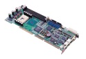
The SBC (Single Board Computer) vs. motherboards
What are the key advantages of using a SBC?
Another key area of concern is the availability of expansion slots. Many of today’s motherboard type systems do not offer as many ISA/PCI expansion slots as they did in the past. In fact, the ISA slot has virtually disappeared from the latest boards available today.
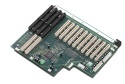
The Single Board Computer or SBC contains all the functionality of a conventional motherboard only designed onto a single plug-in type card, which looks similar to a standard ISA/ PCI card. This SBC plugs directly into what is referred to as a “Passive Backplane”. The Backplane is simply a combination of ISA/PCI expansion slots into which the SBC and other cards are inserted. There are many different configurations of Backplanes available ranging from a couple of slots up to 20 or more.Utilizing SBC and Backplane technology has several key and distinct advantages.
- Available ISA/PCI expansion slots for add-in cards
Lower mean time to repair (MTTR). System’s can be upgraded or repaired in seconds
Better configuration control and longer product life cycle and technical support
Designed for 24 hour 7 day operation
For more information on Industrial Computer standards checkout PICMG at: http://www.picmg.org
- Available ISA/PCI expansion slots for add-in cards
-
WHAT IS A “U” or more specifically a “RACK UNIT”?
As in 1U, 2U, 4U … etc
A “Rack Unit” or “U” is an Electronic Industries Alliance or more commonly “EIA” standard measuring unit for rack mount type equipment. This term has become more prevalent in recent times due to the proliferation of rack mount products showing up in a wide range of commercial, industrial and military markets. A “Rack Unit” is equal to 1.75″ in height. To calculate the internal useable space of a rack enclosure you would simply multiply the total amount of Rack Units by 1.75″. For example, a 44U rack enclosure would have 77″ of internal usable space (44 x 1.75).
Stealth manufactures computers and peripherals that are designed to fit into a standard EIA size rack enclosures. Stealth’s Rackmount PCs, LCD Monitors and Keyboards are available in many sizes and configurations. The slim space saving series rack products are available in 1U (1.75″) and 2U (3.5″) in overall height. Since rack space is at a premium these slim products represent significant cost savings to the end user. Standard rackmount products are available in 1U, 2U, 4U, 5U and 6U configurations.
-
What is a NIT?
A NIT is a measurement of light in candelas per meter square (Cd/m2)
For an LCD monitor it is brightness out of the front panel of the display. A NIT is a good basic reference when comparing brightness from monitor to monitor. Most desktop LCD’s or Notebook LCD’s have a brightness of 200 to 250 Nits. These standard LCD’s are not readable in direct or even indirect sunlight as they become washed out.
-
What is a Viewing Angle and why does it matter?
The viewing angle is the angle at which the image quality of an LCD degrades and becomes unacceptable for the intended application. Viewing angles are usually quoted in horizontal and vertical degrees with importance dependent on the specific application. As the observer physically moves to the sides of the LCD, the images will degrade in three ways. First, the luminance drops. Second, the contrast ratio usually drops off at large angles. Third, the colors may shift. Most modern LCD’s have acceptable viewing angles even for viewing from the sides.
For LCD’s used in outdoor applications, defining the viewing angle based on CR alone is not adequate. Under very bright ambient light conditions the display is hardly visible when the screen luminance drops below 200 nits. Therefore, the viewing angles are defined based on both the CR and the Luminance.
-
What is a Watchdog Timer?
A watchdog timer is a piece of hardware, often built into a Single Board Computer (SBC) or embedded PC that can cause a reset when it determines that the system has either hung up or is no longer executing the correct sequence of code.
A properly designed watchdog mechanism should, at the very least, catch events that hang the system. In electrically noisy environments, a power glitch may corrupt the program counter, stack pointer, or data in RAM. The software could crash, even if the code is completely bug free. This is precisely the sort of transient failure that watchdogs will catch.
Bugs in software will cause systems to hang, therefore it is better to fix the root cause rather than relying on a watchdog timer. In complex embedded systems it may not be possible to guarantee that there are no bugs, however by using a watchdog you can prevent those bugs from hanging the system indefinitely.
Conclusion
A good watchdog system requires careful consideration of both software and hardware. Make certain to decide early on in the design process how you intend to use it and when a failure is detected you will reap the benefits of a more robust system. -
What is considered a true sunlight readable or outdoor readable LCD?
First, the display screen on a sunlight readable/outdoor readable LCD should be bright enough so that the display is visible in direct or strong sunlight. Second, the display contrast ratio must be maintained at 5 to 1 or higher.
Although a display with less than 500 nits screen brightness and a mere 2 to 1 contrast ratio can be read in outdoor environments, the quality of the display will be dreadfully poor and not get the desired information across effectively. A true sunlight readable display is normally considered to be an LCD with at least 1000 nits of screen brightness and a contrast ratio greater than 5 to 1. In outdoor environments under the shade, such a display can provide an excellent image quality.
-
What is Contrast Ratio (CR)?
Contrast ratio (CR) is the ratio of luminance between the brightest “white” and the darkest “black” that can be produced on a display. CR is another influence of perceived picture quality. If a picture has high CR, you will consider it to be sharper and crisper than a picture with lower CR. For example, a typical newspaper picture has a CR of about 5 to 7, whereas a high quality magazine picture has a CR that is greater than 15. Therefore, the magazine picture will look better even if the resolution is the same as that of the newspaper picture.
A typical AMLCD exhibits a CR of approximately 300 to 700 when measured in a dark room. The CR on the same unit measured under ambient illumination is drastically lowered due to surface reflection (glare). For example, a standard 200 nit LCD measured in a dark room has a 300 CR, but will have less than a 2.0 CR under intense direct sunlight. This is due to the fact that surface glare increases the luminance by over 200 nits both on the “white” and the “black” that are produced on the display screen. The result is the luminance of the white is slightly over 400 nits, and the luminance of the black is over 200 nits. The CR ratio then becomes less than 2 and the picture quality is drastically reduce and not acceptable.
-
What is Dot Pitch or Pixel Pitch?
The dot pitch specification for a display monitor tells you how sharp the displayed image can be. The dot pitch is measured in millimeters (mm) and a smaller number means a sharper image. In desk top monitors, common dot pitches are .31mm, .28mm, .27mm, .26mm, and .25mm. Personal computer users will usually want a .28mm or finer. Some large monitors for presentation use may have a larger dot pitch (.48mm, for example). Think of the dot specified by the dot pitch as the smallest physical visual component on the display. A pixel is the smallest programmable visual element and maps to the dot if the display is set to its highest resolution. When set to lower resolutions, a pixel encompasses multiple dots.
-
What is HMI / SCADA Software?
HMI
Human Machine Interface software gives machine operators a way to interact with and manage a system. This interaction is through a graphical user interface (GUI).
SCADA
Supervisory control and data acquisition (SCADA) is a control system architecture that uses computers, networked data communications and graphical user interfaces for high-level process supervisory management, but uses other peripheral devices such as programmable logic controllers (PLCs) and discrete PID controllers to interface to the process plant or machinery.
The operator interfaces which enable monitoring and the issuing of process commands, such as controller set point changes, are handled through the SCADA supervisory computer system. However, the real-time control logic or controller calculations are performed by networked modules which connect to the field sensors and actuators.
Examples:
- Both large and small systems can be built using the SCADA concept. These systems can range from just tens to thousands of control loops, depending on the application. Example processes include industrial, infrastructure, and facility-based processes, as described below:
- Industrial processes include manufacturing, Process control, power generation, fabrication, and refining, and may run in continuous, batch, repetitive, or discrete modes.
- Infrastructure processes may be public or private, and include water treatment and distribution, wastewater collection and treatment, oil and gas pipelines, electric power transmission and distribution, and wind farms.
- Facility processes, including buildings, airports, ships, and space stations. They monitor and control heating, ventilation, and air conditioning systems (HVAC), access, and energy consumption.
-
What is Intrinsically Safe?
Intrinsic safety is a protection concept deployed in sensitive and potentially explosive atmospheres. Intrinsic safety relies on the equipment being designed so that it is unable to release sufficient energy, by either thermal or electrical means, to cause an ignition of a flammable gas.
Intrinsically safe is achieved by limiting the amount of power available to the electrical equipment in the hazardous area to a level below that which will ignite the gases.
In order to have a fire or explosion, fuel, oxygen and a source of ignition must be present. An intrinsically safe system assumes the fuel and oxygen is present in the atmosphere, but the system is designed so the electrical energy or thermal energy of a particular instrument loop can never be great enough to cause ignition.
Traditionally, protection from explosion in hazardous environments has been accomplished by either using explosion proof equipment which can contain an explosion inside an enclosure, or pressurization and/or purging which isolates the explosive gas from the electrical equipment.
Intrinsically safe equipment cannot replace these methods in all applications, but where possible can provide significant cost savings in installation and maintenance of the equipment in a Hazardous area. The basic design of an intrinsic safety barrier uses Zener Diodes to limit voltage, resistors to limit current and a fuse.
Most applications require a signal to be sent out of or into the hazardous area. The equipment mounted in the hazardous area must first be approved for use in an intrinsically safe system. The barriers designed to protect the system must be mounted outside of the hazardous area in an area designated as Non-hazardous or Safe in which the hazard is not and will not be present.
APPROVALS
Intrinsic safety equipment must have been tested and approved by an independent agency to assure its safety. The customer should specify the type of approval required for their particular application. The most common Agencies involved are as follows:COUNTRY AGENCY
USA – FM, UL
Canada – CSA
Great Britain – BASEEFA
France – LCIE
Germany – PTB
Italy – CESI
Belgium – INEX -
What is Luminance?
Luminance is the scientific term for “Photopic Brightness” which specifies the visual brightness of an object. In layman’s terms, it is commonly referred to as “brightness”. Luminance is specified in candelas per square meter (Cd/m2) or nits. In the US, the British unit Foot-lamberts (fL) is also frequently used. To convert from fL to nits, multiply the number in fL by 3.426 (i.e. 1 fL = 3.426 nits).
Luminance is an influential factor of perceived picture quality in an LCD. The importance of luminance is enhanced by the fact that humans will react more positively to a brightly illuminated screen. In indoor environments, a standard active-matrix LCD with a screen luminance of around 250 nits will look good. In the same scenario an LCD with a luminance of 1,000 nits or more will look utterly captivating.
-
What Is RoHS?
What is it and why I should care
by Ray FranklinRoHS stands for Restriction of use of Hazardous Substances (ref. 1). The acronym is pronounced Rose, Roz, Ross, or is spelled out, depending on the speaker’s preference. RoHS is a directive issued January 27, 2003 by the European Commission (EC). It directs European Union (EU) member nations to enact local legislation by August 13, 2004, which will implement the RoHS directive as regulatory requirements before the activation date of July 1, 2006. And that means what?
The directive is a legally binding document, for the EU member nations. It establishes regulations at the EU level, which flow to each member nation. Each government must pass its own laws, patterned after the RoHS directive, and do so by a deadline.
RoHS is part of a growing wave of environmental regulations or green initiatives. In addition to RoHS for Europe, there are similar regulations being written in China and other Asian nations. Japanese companies have created a non-governmental group to standardize green procurement requirements. In the US, individual states are passing laws restricting some substances and requiring recycling of certain classes of products. A common theme is the so-called “take-back” feature that requires manufacturers to accept old products from consumers and reuse or recycle the items.
The RoHS directive requires that six hazardous substances be removed from all electrical and electronic equipment. The substances may be present incidentally at certain levels as long as they are declared. The six substances are Cadmium (Cd), hexavalent Chromium (CR VI), Lead (Pb), Mercury (Hg), polybrominated biphenyls (PBB) and polybrominated diphenyl ethers (PBDE). The maximum concentration of Cd is 0.01% by weight of homogeneous material, and 0.1% by weight for the other five substances. “Homogeneous material” means a material that cannot be mechanically disjointed into different materials (ref. 2). A substance is “present incidentally” if it was not intentionally added.
Some exemptions are declared in the RoHS annex, such as Hg in fluorescent lamps, Pb in certain alloys, and Pb in solder for servers (until 2010). All the details are in the RoHS directive text, with discussion and explanation in the dti RoHS guidance notes.
It all sounds pretty straightforward. There are, however, some kinks. For one, the EU member nations have not followed through and produced legislation. The August 13 deadline is long past and only a few countries have passed legislation (ref 3). This delay is creating uncertainty among corporations striving for compliance. Compounding the confusion, local legislation could tighten restrictions and possibly remove exemptions. Any company counting on a particular exemption could run into trouble in countries that nullified the exemption. Furthermore, the EC failed to meet its own October 2004 deadline of finalizing the directive.
Though the regulatory climate is still unsettled, a few certainties have popped up. Compliance is not optional. If you don’t face regulation directly, your customers probably will, and they will push the requirements down to you. The safest strategy is to comply with the most stringent requirements – aim for RoHS with no exemptions. You are not alone. Every other business is in the same boat, and industry groups are working hard to formulate standards for compliance. Use the links on the RoHSwell home page to research RoHS in greater depth. Form your own plan, and get compliant.
References
1. From directive 2002/95/EC, of the European Parliament.
2. From dti RoHS Regulations, Government Guidance Notes, Consultation Draft, July 2004.
3. The Perchards Report, summary of the transposition of the WEEE and RoHS directives into law by EU member states, January 2005.


